17 Tips on the Designing Key Points of Plastic Injection Mould,Plastic Injetion Mould Maker

5 Tips on The Development of New Product .
January 5, 2018
What kind of intelligence can be equipped with Industrial Rugged Tough Tablet PC ?
February 1, 201817 Tips on the Designing Key Points of Plastic Injection Mould,Plastic Injetion Mould Maker

Plastic injection mould design,mould design,double injection mould design,product development
Plastic Injection Mould design:17 Tips on the Designing Key Points of Plastic Injection Mould,Plastic Injetion Mould Maker
1. Plastic Injection Mould design: the open mold direction and the classification line
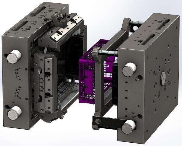
At the beginning of the Plastic Injection Mould design, each injection product must first determine its open mode direction and the classification line, to ensure that as far as possible to reduce the core-pulling slider mechanism and eliminate the impact of the split line on the appearance.
1.1, the direction of the open mold, the product of the reinforcement, buckle, raised and other structures as far as possible designed to be consistent with the direction of the open mold, to avoid pulling the core to reduce the stitching, prolong the life of the mold.
1.2, the direction of the open mode is determined, you can choose the appropriate classification line, to avoid the open mold direction of the inverted, to improve the appearance and performance.
2. demoulding slope/draft angle
2.1, the appropriate demoulding slope can avoid the product nap (bows).
Smooth surface of the stripping slope should be ≥ 0.5 degrees, fine skin lines (sand surface) surface is greater than 1 degrees, coarse skin pattern surface is greater than 1.5 degrees. Plastic Injection Mould design
2.2, the appropriate demoulding slope can avoid the product top injury, such as top white, top deformation, top broken.
2.3, deep cavity structure product design when the external surface gradient as far as possible than the internal surface gradient to ensure that the mold core injection molding, the uniform thickness of the product, and to ensure that the product openings in the material strength. Plastic Injection Mould design
3. the product wall thickness
3.1, all kinds of plastic have a certain wall thickness range, general 0.5~4mm, when the wall thickness of more than 4mm, will cause the cooling time is too long, resulting in reducing the problem, should be considered to change the product structure. Plastic Injection Mould design so important .
3.2, wall thickness will cause the surface shrinkage.
3.3, wall thickness will cause pores and weld marks.
4. Reinforcing tendons
4.1, strengthen the rational application of tendons, can increase product rigidity, reduce deformation.
4.2, the thickness of the reinforcement must ≤ (0.5~0.7) t product wall thickness, or cause the surface shrinkage.
4.3, the reinforcement of the single slope should be greater than 1.5 ° to avoid top injury.
5. Rounded Corners
5.1, fillet too small may cause product stress concentration, resulting in product cracking.
5.2, the rounded angle is too small may cause the mold cavity stress concentration, causes the cavity to crack.
5.3, set a reasonable fillet, but also can improve the mold processing technology, such as the cavity can be directly used with R cutter Milling, and avoid low efficiency of the electrical processing.
5.4, the different rounded angle may cause the classification line movement, should combine the actual situation to choose the different rounded angle or the clear angle for the Plastic Injection Mould design
6, Hole
6.1, the shape of the hole should be as simple as possible, generally take round.
6.2, the hole axial and open mode direction consistent, can avoid pulling core.
6.3. When the length diameter ratio of the hole is greater than 2 o’clock, the demoulding inclination should be set.
The diameter of the hole should be calculated according to the size of the path (maximum solid size).
6.4. The length diameter ratio of blind hole is generally not more than 4.
Anti-hole needle punching and bending
6.5 The distance between hole and product edge is generally larger than aperture size.
7. Seven, the injection mold core-pulling, slider-block mechanism and avoid
7.1, when the plastic parts according to the direction of the open mold can not be smooth demoulding, the design of core-pulling slider mechanism.
The slider of core-pulling mechanism can form complex product structure, but it is easy to cause the defects such as stitching, shrinkage and so on, and shorten the die life.
7.2, Design injection molding products, if no special requirements, as far as possible to avoid core-pulling structure.
For example, the direction of the hole axial and the rib is changed to the direction of opening mode, and the cavity core is used to touch and wear.
8. one-body integrated hinge
8.1, the use of PP material toughness, the hinge can be designed and integrated products.
8.2, as the hinge of the film size should be less than 0.5mm, and maintain uniformity,
8.3. When the integral hinge is molded, the gate can only be designed on one side of the hinge.
9. Inserts
9.1, insert inserts in the injection molding products can increase local strength, hardness, dimensional accuracy and set small threaded holes (axes) to meet a variety of special needs.
It also increases the cost of the product.
9.2, the inlay is generally copper, can also be other metal or plastic parts.
9.3, insert in the embedded plastic parts should be designed to stop and pull-out structure.
such as: rolling flowers, holes, bending, flattening, shaft shoulder and so on.
9.4, the surrounding plastic should be properly thickened to prevent plastic parts stress cracking.
9.5, design inserts, should take full account of its in the Mold positioning mode (hole, pin, magnetic)
10. logo postion
Product identification is generally set in the product interior surface more flat, and the use of convex form, the selection of the normal and open mold direction ruler may be consistent with the identification of the surface, you can avoid the pull injury.so it is clear they are key points for Plastic Injection Mould design
11 . precision of injection parts
Due to the uneven and uncertain shrinkage rate of injection molding, the precision of injection parts is obviously lower than that of metal parts, so it is not easy to apply the tolerances of mechanical parts according to the standard. Our country also released in 1993 gb/t14486-93 “Engineering Plastics molded plastic parts dimensional tolerance”, The designer may determine the dimensional tolerances of the workpiece according to the requirements of the plastic raw materials and parts used.Also are key points for Plastic Injection Mould design
At the same time, according to the factory comprehensive strength, peer product design accuracy to determine the appropriate design tolerance accuracy.
12. Deformation of injection molded parts Improve the rigidity of injection molding product structure, reduce deformation. As far as possible to avoid the plate structure, reasonable set flanging, concave-convex structure.
Set reasonable reinforcement.
13. Buckle Position
1, the buckle device design into a number of buckle at the same time common, so that the overall device will not be due to individual buckle damage and can not operate, thereby increasing its service life, and then more Test filter plus rounded corners, increase strength. 2, the tolerance of the relevant size of the buckle requirements are very rigorous, the position of the flip is too easy to form a buckle damage;
The solution is to reserve the way to easily add plastic mode to achieve.
14, welding (Hot plate welding, ultrasonic welding, vibration welding)
14.1, the use of welding, can improve the strength of the connection.
14.2, the use of welding, can simplify product design.
15. The contradiction between process and product performance should be considered rationally .
15.1The design of injection molding products must take into account the product appearance, performance and process contradictions.key points for Plastic Injection Mould design
Sometimes sacrificing some of the process, you can get good appearance or performance.
15.2 Structural design can not avoid the injection defects, as far as possible to make the defect occurred in the product’s hidden parts.
16. The relationship between the diameter of the screw cylinder and the tapping screw
Self Tapping screw cylinder diameter
M2 1.7mm
M2.3 2.0mm
M2.6 2.2mm
M3 2.5mm ,key points for Plastic Injection Mould design
17, Boss design principles:
17.1, the pillar as far as possible not to use alone, should try to connect to the outer wall or with the reinforcement to use together, the aim is to strengthen the strength of the pillars and make the rubber flow smoother.
17.2, the height of the pillar is generally not more than twice times the diameter of the pillar.
Because of the high pillars will lead to plastic parts trapped gas (long time can cause air holes, coke, filling insufficient, etc.).key points for Plastic Injection Mould design
17.3, if the height of the pillar is more than twice times the diameter of the pillar, especially away from the outer wall of the pillars, strengthen the strength of the pillars of the method is the use of reinforcement.key points for Plastic Injection Mould design
17.4, the boss of the shape of the circle as the main, other shapes are not easy to process
17.5, boss position can not be too close to the angle or the outside side of the wall, should be with the outer wall of the product to maintain a distance
17.6, the boss circumference can be removed part of the thick meat (that is, open the crater) to prevent shrinking subsidence,they are key points for Plastic Injection Mould design
17. 7, Boss’s dial mode angle: Usually take 0.5 °, take 0.5° or 1
Origina Copyright belong to Sachimolds.com .A IRL Group Company .If you want to copy ,pls mark the original link and contact us for copyright
Or You can contact our sister company IRL Electronics Co.,Ltd for your info:www.irlelec.com


